

On Board Charger Electric Vehicle
Topic: On Board Charger Electric Vehicle

On Board Charger Electric Vehicle
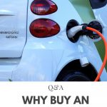
Even as the globe prepares to unleash an EV revolution, the rate of adaptation remains modest. Despite being a greener, smoother, and less expensive method of transportation, EVs do not appear to be practicable at this time.
There are two reasons for this: cost and ecosystem. EVs are currently priced similarly to gasoline automobiles, making them less appealing for purchasers. However, advances in battery technology and government incentives are projected to reduce the cost of EVs in the future.
The second element is that there is no appropriate ecology for buyers to use an Electric Vehicle without difficulty. When I say “ecosystem,” I’m talking to the charging stations where you can recharge your electric vehicle when the battery runs out.
Consider driving a gasoline vehicle in a town where there are no gas stations and the only place to fill up is at home; add to that the fact that charging a typical EV takes at least 6-8 hours.
Many firms, such as Tesla, EVgo, and ChargePoint, have already recognised this issue by establishing charging stations across the country. With countries like the Netherlands promising to phase out petrol engines by 2035, it’s safe to assume that the highways of the future will be dominated by electric vehicles rather than internal combustion engines and that a slew of EV charging stations will spring up all over the place.
But how do EV charging stations function? Is it possible to charge all sorts of electric vehicles at a single charging station? What are the different types of EV chargers?
What are the protocols for EV chargers? In this post, we’ll look at the answers to all of these concerns, as well as what an Electric Vehicle Charging Station is and the subsystems that make it work.
Before continuing, you should familiarise yourself with the batteries used in electric vehicles and how the battery management system operates within them.
Equipment for supplying electric vehicles (EVSE)
Electric Vehicle Supply Equipment refers to the equipment that makes up an electric vehicle charging station (EVSE). The word is more widely used and refers solely to charging stations. ECS, which stands for Electric Charging Station, is another name.
An EVSE is a device that uses the grid to charge a battery pack; these battery packs can be found in either an electric vehicle (EV) or a plug-in electric vehicle (PEV) (PEV). These EVSE’s power, connector, and protocol will differ depending on their design, which we shall explore in this post.
Charging Stations and On-Board Chargers
Before going to a charging station, knowing what’s inside the electric vehicle and which portion the charger will be linked to is necessary. Most modern EVs include an On-Board Charger (OBC), and the manufacturer may also include a Charger with the vehicle.
The consumer can use these chargers, along with the on-board charger, to charge his EV from his home power outlet as soon as they bring it home. However, because these chargers are pretty basic and lack advanced capabilities, charging a conventional EV would typically take 8 hours.
EV Charging Station Types (EVSE)
AC charging stations and DC charging stations are the two main charging stations.
As the name implies, an AC charging station provides AC power from the grid to the EV, converted to DC and charged using the on-board charger. These chargers, also known as Level 1 and Level 2 chargers, are used in both home and commercial settings. The advantage of an AC charging station is that the on-board charger regulates the voltage and current as needed for the EV.
Thus, the charging station does not need to communicate with it. The drawback is that it has a low output power, which lengthens the charging time.
AC DC charging Station obtains AC power from the grid, converts it to DC voltage, and uses it to charge the battery pack directly by bypassing the on-board charger (OBS) (OBS).
These chargers typically provide a high voltage of up to 600V and a current of up to 400A, allowing the EV to be charged in under 30 minutes versus 8-16 hours with an AC charger.
These are also termed Level 3 chargers and are generally known as DC Fast Chargers (DCFC) or Superchargers. The benefit of this charger is its quick charging time, but the drawback is its complicated engineering, which requires it to communicate with the EV to charge it correctly and safely.
The EVSE sends DC straight to the battery pack, skipping the OBS. The EVSE is arranged in stacks to deliver a high current, but a single stack will not supply a high currently due to power switch constraints.
Typically, Level 1 chargers are intended for domestic usage; these are the chargers packaged with the EV and can be used to charge the EV using ordinary household power outlets.
So they function with a single-phase AC power and can output anything from 12 to 16 amps, and it takes roughly 17 hours to charge a 24kWH electric vehicle. In a charging station, a Level 1 charger plays a minor role.
The Level 2 charger is an upgrade to the Level 1 charger. It can be placed in the home on special request if it has a split-phase power supply or is used in public/commercial charging stations.
Due to the high input voltage, these chargers can produce up to 80A output current and charge an EV in 8 hours. Level 3 chargers, often known as Superchargers, are only intended for use at public charging stations.
They require polyphase AC grid input and consume more than 240 kW, over ten times the power of a conventional air conditioning unit in our home. As a result, special approval from the grid is required for these chargers to function.
Because the AC/DC and DC/DC conversion take place within the EVSE, the Level 2 and Level 3 chargers are more efficient than the Level 1 charger. A Level 2 or Level 3 charger cannot be built inside an EV due to its large size and complexity, increasing the weight and lowering the EV’s efficiency.
On Board Charger Electric Vehicle
The DC/DC converter is the heart of the two-stage Onboard Charger for electric vehicles. The phase-shifted full-bridge soft-switching DC/DC converter currently has lagging leg commutation, voltage fluctuation on the transformer’s secondary side, and low efficiency.
This study proposes a full-bridge DC/DC converter with two clamp diodes and synchronous rectification. Clamping diodes control voltage oscillations on the transformer’s secondary side and give commutating energy to the lagging leg. Synchronous rectification lowers the switching device’s loss.
The operating principle and control mechanism of the DC/DC converter is investigated, and the switching device loss is estimated.
The simulation and experimental results show that, when compared to a traditional DC/DC converter, the voltage impulse on the secondary side of the transformer is smaller, the efficiency is higher, and the soft switch can be implemented over a wide load range, meeting the requirement for fast charging of vehicle-mounted batteries.
Provide an overview
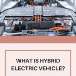
Electric vehicles (EVs) have grown in popularity due to their high efficiency and pollution-free benefits. As the number of electric vehicles grows, the technological demand for onboard chargers increases.
The onboard charger (OBC) must meet the requirements of high power density, high charging efficiency, and intense heat dissipation due to the limited internal area. PFC converter and isolated DC-DC converter are included in a two-stage OBC.
The first converts AC to DC, while the second delivers a wide range of DC for charging the vehicle’s batteries. The primary research goals for EV onboard converters are to improve operational efficiency and reduce volume.
PFC research is relatively established, with prior research achieving an efficiency of over 98 per cent. As a result, the DC-DC converter’s design and operation significantly impact total efficiency and power density.
High-frequency switching converters are now frequently employed in DC-DC converters. The switching frequency is usually measured in tens of kHz. Although raising switching frequency reduces equipment volume, it also causes increased switching loss, decreased efficiency, and increased electromagnetic interference.
To address these issues, soft switching solutions such as ZVS, ZCS, and LLC have emerged. Using this technology in a traditional switching power supply architecture can reduce switching loss and noise interference of power switching devices in the high-frequency state of the converter, improving efficiency and power density while also reducing the converter’s volume and weight.
Full-bridge PWM and full-bridge resonant circuits are two traditional DC-DC converter topologies utilised in OBC (including LLC resonance and series resonance). Switchless off voltage spike and low circulating current power are two advantages of the LLC converter.
When the output voltage range of a DC-DC converter is combined with the charging curve of vehicle batteries, the output voltage range is widened, the converter’s switching frequency deviates substantially from the resonant frequency, and the system loses increases.
The typical full-bridge PWM converter has substantial reactive power circulation. It cannot perform soft switching under a light load, but it can adapt to a wide output voltage range and fixed switching frequency.
As a result, a phase-shifted full-bridge converter with a controllable auxiliary current is presented, achieving full-load soft switching of switching transistors at a high cost and with difficult control.
The reverse recovery loss of the rectifier diode can be reduced by controlling the secondary side of the transformer with phase-shifting control. However, the efficiency is low at full load.
This paper proposes an improved ZVS phase-shifted full-bridge DC/DC converter. The voltage oscillation of the secondary rectifier is eliminated using two clamping diodes. To reduce system losses, a synchronous rectifier (SR) is used. Finally, in the laboratory, an experimental prototype is produced.
Battery Model and Onboard Charging Method for Electric Vehicles
Three-component lithium batteries and lithium iron phosphate batteries are already available for electric vehicles. The three-component lithium batteries, primarily utilised in Tesla electric vehicles, offer a high energy density but low charge current and rapid capacity attenuation.
Lithium iron phosphate batteries are frequently employed in many electric cars because of their high charge-discharge current, slow capacity attenuation, and high safety.
Structure of the Circuit
OBC has a single-stage structure and a two-stage structure, depending on the charger converter topology. The single-stage structure has the advantages of a simple structure and inexpensive cost.
Still, it only has a one-stage conversion, which limits the output voltage range and the effects of power factor, current harmonic suppression, and conversion efficiency.
AC-DC converters are split into AC-DC converters and DC-DC converters based on their capacity to suppress input current harmonics, improve power factor, and process power.
The former AC-DC converter typically employs a Boost circuit for power factor adjustment, whereas the latter DC-DC converter typically uses an isolation converter. It produces DC with a low load ripple coefficient to ensure the converter’s safety. The research investigates a two-stage car charger.
Strategy for Charging
Because electric vehicles rely on vehicle-mounted batteries for power, adopting charging methods that can achieve rapid charging while causing minimal damage to battery life is critical for their adoption.
The most common battery charging methods are constant current charging, constant voltage charging, and stage charging. Constant current charging is simple to use and control however the charging time will be excessive if the charging current is too low.
If the charging current is set too high, it is easy to overcharge at a later stage of charging, causing significant damage to the battery plate and reducing battery life. The constant voltage charging method is straightforward to use and avoids the problem of the battery overcharging throughout the charging process.
The charging current is higher in the early stages of charging due to the lower electromotive force at both ends of the battery. The current shock will cause the battery plate to bend and the battery’s temperature to rapidly rise, reducing the battery’s lifespan.
Furthermore, if the charging voltage is set too low, the battery will not be charged correctly, resulting in shorter battery life. A two-step charging method and a three-stage charging method are the most common stage charging methods.
The constant current charging that occurs before the battery is charged is the two-stage charging process. It is switched to constant voltage charging when the voltage at both ends of the battery reaches a particular amplitude.
The two-stage charging method combines the benefits of constant current and constant voltage charging methods, eliminates the problems of excessive charging current in the early stages and easy overcharging in the later stages, and has a high charging efficiency that can meet the charging demand of lithium iron phosphate batteries. In this study, the two-stage charging approach is used.
Nonconventional on-board charger for electric vehicle propulsion batteries
Electric vehicles (EVs) are required to reduce air pollution in heavily populated metropolitan areas. Battery chargers must provide the DC voltage required to charge the high-energy battery batteries used in EVs.
This paper discusses an on-board battery charger configuration that is entirely based on the use of the EV motor drive’s power components. The proposed method perfectly matches desired properties for EV battery chargers such as minimum volume, cheap cost, high efficiency, and high reliability.
The proposed on-board charger configuration has been fitted on a prototype electric scooter being developed for the Far East markets. The on-board charger prototype’s design analysis and experimental results are presented.
On-board electric vehicle battery charger with enhanced v2h operation mode
This study presents an on-board Electric Vehicle (EV) battery charger with an improved Vehicle-to-Home (V2H) operation mode. An on-board bidirectional battery charger prototype was modified for this purpose, allowing Grid-to-Vehicle (G2V), Vehicle-to-Grid (V2G), and V2H operation modes.
The hardware topology and control algorithms of this battery charger are given throughout the study. The concept underlying this study is the use of the on-board bidirectional battery charger as an energy backup device in a power loss.
Two methodologies for identifying power outages were compared: one based on the half-cycle RMS calculation of power grid voltage, and the other on estimating the RMS value using a Kalman filter.
The testing findings were achieved using the on-board EV battery charger in the G2V, V2G, and V2H modes of operation. The results demonstrate that utilising a Kalman filter for power outage detection is up to 90% faster than the other technique. This also allows for a speedier transition between operation modes in the event of a power interruption.
Function of on board charger in electric vehicle
Chargers for On-Board Devices (OBC)
Each consumer category has distinct EVSE requirements. The needs of an EV charging station vary depending on whether it is used for residential, business, or fleet charging. Every setup is unique, and it is determined by the capacity, kind, number of charging stations, and features necessary.
On-board chargers in EVs alleviate a common issue among EV owners. It enables them to charge their vehicle based on the availability of alternating current power. It is unnecessary to use an EV charging station to charge the vehicle.
The on-board charger transforms grid power into AC power to charge the EV battery. The on-board charger adapters allow EV owners to charge their batteries at home or any other charging station.
In electric vehicles, an on-board charger is a unit that contains a range of signal conditioning solutions, integrated high voltage isolation AC-DC converters, AC rectifiers, dual bridgeless power factor correction (PFC), gate drivers, error amplifiers, and many more power electronic components.
On-board chargers include the following main features:
Efficiency: The most recent on-board chargers are compliant with worldwide electric standards and can be readily installed in an electric car. They are very efficient because they take up minimal space in a car and shorten the charging time of an EV battery.
Power Handling Capacity: The on-board chargers can handle a wide range of input voltages and have power handling capacities ranging from 3 kW to 22 KW.
Two-way Charging: A two-way on-board charger, also known as a bidirectional on-board charger, works in two directions in an electric car. On the one side, they transfer DC power from EVSEs to a vehicle’s battery; on the other hand, they deliver electricity back to the grid (V2G). The bidirectional on-board charger can also be used as a backup power source for home appliances and other electric cars.
People Also Ask:
On-board charger electric vehicle PDF
The low-voltage (LV) battery charging circuit is used for an active power decoupling function in this paper’s single-phase on-board battery charger (OBC) for plug-in electric cars (EVs).
What is on board charger for electric vehicle?
On-board chargers (OBC) enable plug-in hybrid (PHEV) and battery electric vehicles (BEV) to charge everywhere there is alternating current (AC), not just at charging stations. Eaton’s efficient OBC designs help manufacturers reduce time, cost, and risk by providing rapid, innovative charging capability and packaging flexibility with proven designs.
Recommended Articles:

[…] On Board Charger Electric Vehicle […]